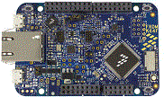
FRDM-K64F

-
Core
Cortex-M4
-
Device
MK64FN1M0VLL12 -
CMSIS Pack
FRDM-K64F_BSP
-
log_bm
µVision AC6The log demo is used to demonstrate how to use log component. The main function of the demo is to prompt the LOG level string according to the user input log level command.
Download Pack -
lptmr
µVision AC6The LPTMR project is a simple demonstration program of the SDK LPTMR driver. It sets up the LPTMRhardware block to trigger a periodic interrupt after every 1 second. When the LPTMR interrupt is triggereda message a printed on the UART terminal and an LED is toggled on the board.
Download Pack -
mcg_fee_blpe
µVision AC6The fee_bple example shows how to use MCG driver to change from FEE mode to BLPE mode: 1. How to use the mode functions for MCG mode switch. 2. How to use the frequency functions to get current MCG frequency. 3. Work flow Boot to Fee mode from default reset mode Change from FEE -> FBE -> BLPE Change back BLPE -> FBE -> FEE Get System clock in FEE mode to blink LEDIn this example, because the debug console's clock frequency may change,so the example running information is not output from debug console. Here theLED blinks to show that the example finished successfully.
Download Pack -
mcg_fee_blpi
µVision AC6The fee_bpli example shows how to use MCG driver to change from FEE mode to BLPI mode: 1. How to use the mode functions for MCG mode switch. 2. How to use the frequency functions to get current MCG frequency. 3. Work flow Boot to FEE mode from default reset mode Change from FEE -> FBI -> BLPI Change back BLPI -> FBI -> FEE Get System clock in FEE mode to blink LEDIn this example, because the debug console's clock frequency may change,so the example running information is not output from debug console. Here theLED blinks to show that the example finished successfully.
Download Pack -
mcg_fei_blpi
µVision AC6The fei_bpli example shows how to use MCG driver to change from FEI mode to BLPI mode: 1. How to use the mode functions for MCG mode switch. 2. How to use the frequency functions to get current MCG frequency. 3. Work flow Boot to FEI mode from default reset mode Change mode FEI -> FBI -> BLPI Change back BLPE -> FBI -> FEI Get System clock in FEI mode to blink LEDIn this example, because the debug console's clock frequency may change,so the example running information is not output from debug console. Here theLED blinks to show that the example finished successfully.
Download Pack -
mcg_pee_blpe
µVision AC6The pee_bple example shows how to use MCG driver to change from PEE mode to BLPE mode: 1. How to use the mode functions for MCG mode switch. 2. How to use the frequency functions to get current MCG frequency. 3. Work flow Boot to PEE mode from default reset mode Change mode PEE -> PBE -> BLPE Change back BLPE -> PBE -> PEE Get System clock in PEE mode to blink LEDIn this example, because the debug console's clock frequency may change,so the example running information is not output from debug console. Here theLED blinks to show that the example finished successfully.
Download Pack -
mcg_pee_blpi
µVision AC6The pee_bpli example shows how to use MCG driver to change from PEE mode to BLPI mode: 1. How to use the mode functions for MCG mode switch. 2. How to use the frequency functions to get current MCG frequency. 3. Work flow Boot to PEE mode from default reset mode Change mode PEE -> PBE ->FBE -> FBI -> BLPI Change back BLPI -> FBI -> FBE -> PBE -> PEE Get System clock in PEE mode to blink LEDIn this example, because the debug console's clock frequency may change,so the example running information is not output from debug console. Here theLED blinks to show that the example finished successfully.
Download Pack -
mqtt_client_demo
µVision AC5MQTT Client demo (CycloneTCP and CMSIS-RTOS2)
Download Pack -
mqtt_client_demo
µVision AC5MQTT Client demo (CycloneTCP and CMSIS-RTOS2)
Download Pack -
pdb_adc16_trigger
µVision AC6The pdb_adc16_trigger example shows how to use the PDB to generate a ADC trigger.Based on the basic counter, to use the ADC trigger, just to enable the ADC trigger's "milestone" and set the user-defined value for it.After the PDB counter is triggered to start, when the counter pass the "milestone", the ADC's Pre-Trigger would begenerated and sent to the ADC module.In this example, the ADC16 is configured with hardware trigger and conversion complete interrupt enabled.Once it gets the trigger from the PDB, the conversion goes, then the ISR would be executed.
Download Pack
